Anatomy of an Image
Tip
In this article, if a term is vital to describing images in Gaffer, its first occurence will be highlighted in bold.
Gaffer’s image nodes output data that describe a 2D image. In this article, we will outline the structure and terminology associated with an image.
Image properties can be broken into two areas:
- Global properties of the whole image
- Channel data (pixels)
This is merely a conceptual division to help understand how Gaffer processes images: when building graphs, there is no significant practical divide between any of an image’s properties. All of them are subject to modification by image nodes.
Note
Users familiar with OpenEXR will recognize that Gaffer shares many of the same image property terms. The main divergence is that Gaffer refers to them generically as properties rather than attributes.
Image properties
Format
Format describes the image’s output format in pixel width, height, and aspect ratio. Typical values for this correspond to standards such as Full HD, 2K UHD, 4K UHD, etc. Custom formats are also supported.
The format property can be conceived of as the combination of OpenEXR’s display window and pixel aspect ratio attributes.
Display window
Display window is the rectangular region that represents the final boundary of the output image. Its values are the coordinates of the bottom-left and top-right corners of the region.
Pixel aspect ratio
Pixel aspect ratio is a floating-point value that specifies the ratio between the width and height of a pixel. The default value is 1.0 (square pixels), which is the most commonly used. Non-default values would typically only be used when working with anamorphic source images.
Data window
Data window is the rectangular region that defines the usable processing area of the image. Its values are the coordinates of the bottom-left and top-right corners of the region.
The data window differs from the display window in that only the pixels inside it are processed during a node computation. Its position and size are independent of the display window. There are useful rendering applications in making it bigger (overscan rendering, blurring, lens distortion, and camera shake) and smaller (isolating a sub-region of pixels for performance, or cropping out negative space) than the display window.
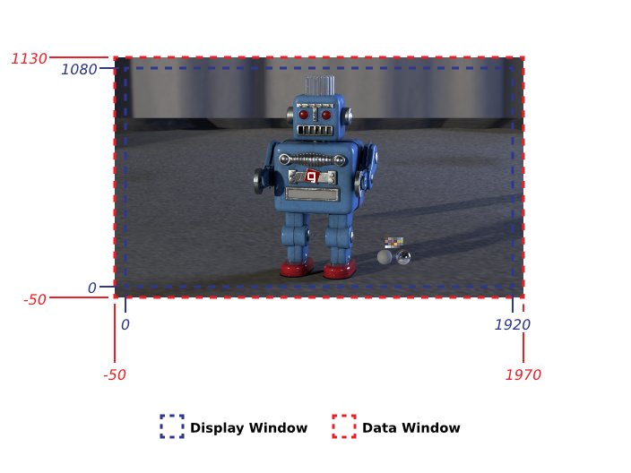
Figure A: The data and display windows for an image with overscan. Notice that there is pixel data beyond the boundaries of the display window.
Metadata
Metadata is a list of arbitrary, strongly typed name-value pairs that represent non-pixel data in the image. A common source of image metadata is Exif/TIFF tags generated by a source image’s camera(s). Compatible metadata types consist of the common string, integer, float, V2i, Box2i, etc. types that are available for Gaffer plugs, and some additional types such as TimeCode, unsigned integers, and vector data types.
Gaffer can read, add, and remove metadata from an image, but it assigns no specific meaning to any particular value. For a node graph to respond to a metadata value, it will need to be accessed by an Expression node.
Note
Gaffer follows the OpenImageIO conventions for metadata naming, as specified in Appendix B of the project’s Programmer Documentation.
Channel names
Channel names is a list of arbitrary names specifying the channels in the image. The default channel names are R, G, B, and A for standard additive color images.
Additional channels are grouped into layers using a prefix-based naming convention. For example, diffuse.R, diffuse.G and diffuse.B are the RGB channels of the diffuse layer. By convention, Z identifies a depth channel, and any other name identifies an auxiliary channel.
Note
Gaffer follows the OpenEXR convention for channel names.
Channel data
Channel data contains each channel’s list of pixel values. Internally, Gaffer represents pixels as 32-bit floating point values, which are converted to and from other bit depths by the Image Reader or Image Writer nodes, as needed.
Channel data contains no positional information. When an image’s pixel data is processed by a computation, the pixels of each channel are grouped into 64x64 pixel tiles, which are arranged in rows and columns to form the complete image. Images can be computed in parallel, on a per-tile, per-channel basis.
Image coordinate system
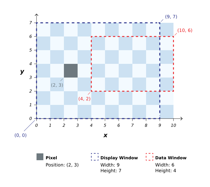
Figure B: A model of the image coordinate system in Gaffer.
Gaffer’s image coordinate system is defined on an integer grid, with the origin in the bottom-left, and one unit equal to one pixel. As y values increase, the image grows upwards. A pixel is referenced by the x and y coordinates of its bottom-left corner.
Pixel areas, such as data and display windows, form a rectangle between the coordinates of the bottom-left corner of their bottom-left pixel and the top-right corner of their top-right pixel.
When sub-pixel values are needed for a process, such as rotating an image on a pivot point, the coordinate system uses floating-point values, with (x + 0.5, y + 0.5) being the pixel centre.
Note
The OpenEXR coordinate system has two counterintuitive aspects:
- As y values increase, the image grows downward.
- Pixel areas do not incorporate the furthest pixel’s outer edge, leading to unintuitive width and height ranges, e.g. 0–1919 and 0–1079 for Full HD.
In order to make manipulating images more intuitive for users, the Gaffer coordinate system differs from these aspects by design.